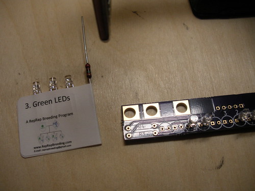
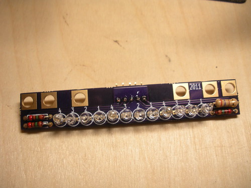
First verify you have all the parts:

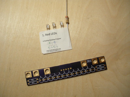
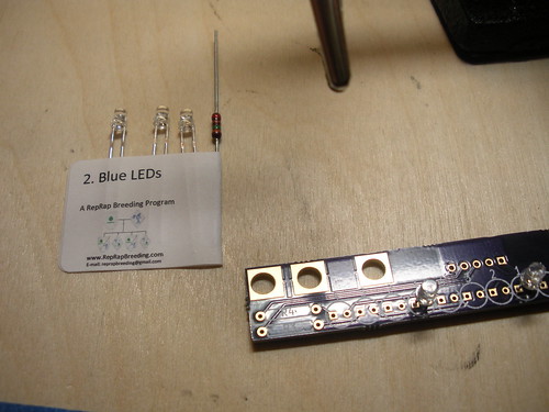
The Red LEDs have a different resistor value than the rest. Ensure that this resistor stays with the Red LEDs.
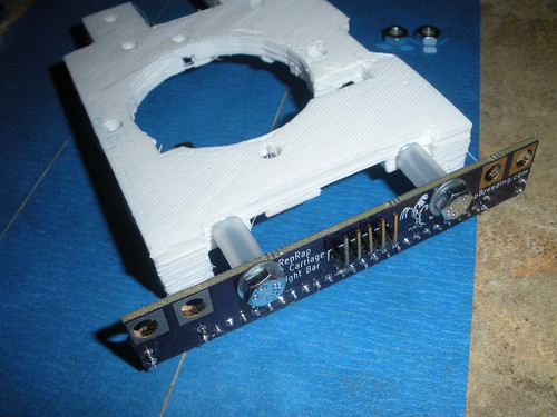
Take the Red LEDs and resistor and bend the resistor leads to fit the holes on the PCB. The Red LEDs go in the spots marked "1" with the long LED leads going to the square shaped pads. The resistor goes in the spot marked "R1."
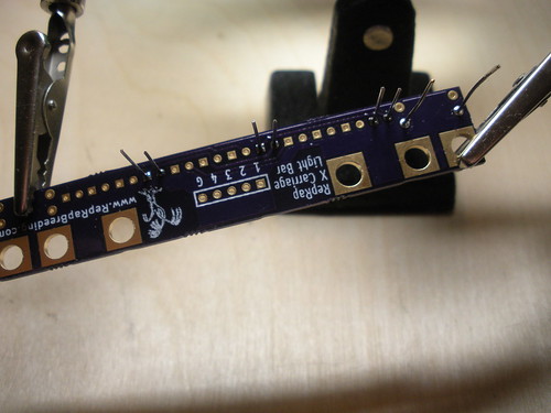
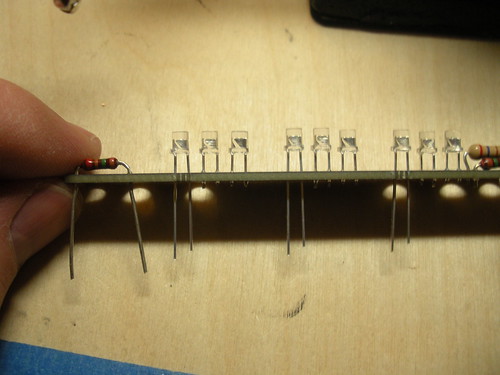
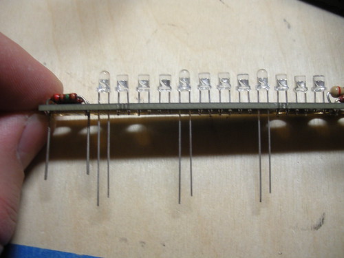
Solder them in place:
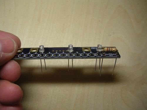
Repeat this for the remaining LEDs taking care to do them one color at a time to avoid mixing up the LEDs. They each have a number on the label that matches a number on the PCB.

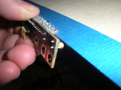
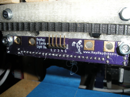
On the opposite side of the board place the 5 pin right angle header
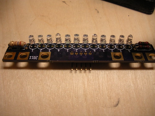
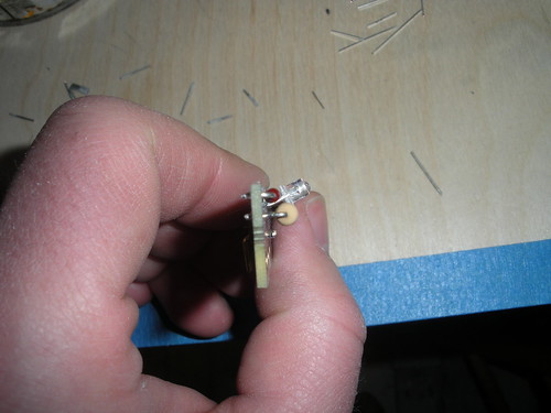
Then using the edge of a table or other flat object gently bend all the LEDs down to a 30-45° angle (The exact angle will depend on your carriage and hot end, so bend them to optimize the light on your print area.)
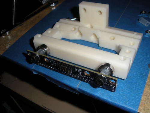
Mount it to your carriage connect the "G" pin to ground and the "1"-"4" pins to switched 12V (1 is Red, etc...).
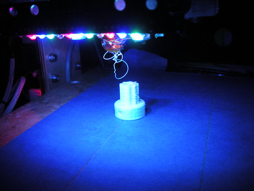
More pictures here


Hey can you please post the part# for the uv led? I would like to switch out the others for uv and want to keep them the same... thanks!!!
ReplyDeleteI do not have a part number for the LEDs I have been using. However they are from cece718 on ebay: http://stores.ebay.com/cece718/3mm-Round-20-25-Degrees-/_i.html?_nkw=UV&_fsub=539830016&_sid=352223206&_trksid=p4634.c0.m322
ReplyDeleteThank you for your interest,
Nick