Tuesday, May 17, 2011

DIY Inkjet Printer

Close-up of carriage

This quarter at the UW we produced some documentation on the development of a DIY inkjet printer.  This was partly in response to the fact that there are no DIY inkjet kits available.  There was a kit available from Parallax however it is no longer made and the main book that was written to go with it is now out of print.

The goal of this project was to develop a low cost, open source inkjet printer utilizing standard inkjet technology, for personal use. This project was partly in response to the fact that there are no DIY inkjet kits available. There was a kit available from Parallax parallax.com/dl/docs/prod/robo/InkjetKitDocs-v1.0.pdf. This kit is no longer made and the book amazon.com/Inkjet-Applications-Matt-Gilliland/dp/0972015930 that was written to use that kit is now out of print.
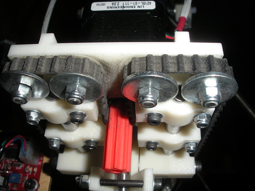
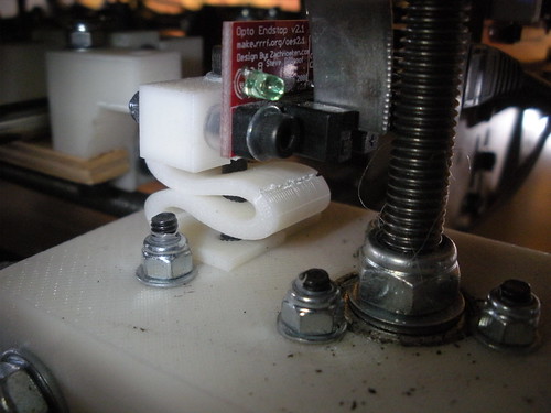
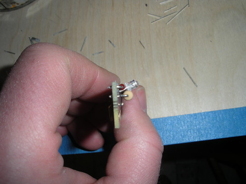
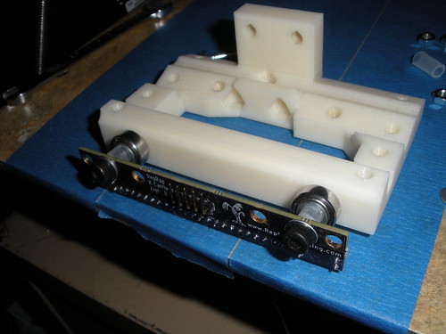
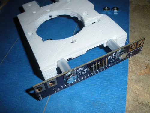
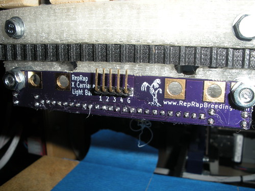
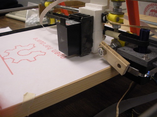
The prototype design used a carriage assembly constructed from steel rods that were assembled using connectors that can be printed on an FDM machine. The entire carriage system is driven along the x-axis by a belt attached to a stepper motor. The print cartridge, taken from an HP point of sale printer, is driven along the y-axis by another stepper motor belt drive. The electronic controls use an Arduino Mega to run all of the printing systems.
The design resulted in a working prototype that fulfills all of the design constraints. The rod frame carriage design is lightweight, easy to assemble and easy to integrate with the other systems. The Arduino used in the electronics has a large library of resources available to perform things like LCD, SD card, and stepper control.
Areas where future work should be focused include making molds and casting printable parts to bring down the overall cost, developing host side software, and optimizing the speed.

The documentation is being released as a thing on Thingiverse, a photo album and a video.

Wednesday, April 6, 2011

The McCormick Code - help the FBI

The FBI currently is asking the public for help in deciphering these paper that were found on Ricky McCormick's dead body in 1999.  I first read about this on PhysOrg and then read the FBI's original write-up.  I felt that maybe I could crack the code but that the chances would be much better if a very large group of people worked together to solve it. Therefore I chose to start a wiki as a tool for collaborative work by anyone and everyone. It is my hope that this will allow us to help the FBI solve this decade old mystery.


This wiki site was started to have a central location to discuss and work on decoding the McCormick Code.  I have setup a Forum and a Theories page to start. I would like to see a page setup for any theory that is come up with. From there it will evolve and grow.

If you think you can help or are just curious please visit, sign up, and help crack the code.  If you have information and want to contact the FBI directly they have a dedicated tip line.

I know that this is a little off topic for a RepRap blog but I think the RepRap community could be a good resource to tap in solving this mystery.

Sunday, April 3, 2011

A Clonedel transplant

It seems that a year of printing parts, 16 offspring plus many other items, has had its toll on Willow.

I also noticed that the filament has not been feeding well resulting in very poor prints.  Looking for the culprit led me to my idler. The original was cracked and when I was talking to Matt at Metrix Create: Space he suggested I replace it with a Clonedel idler.
Clonedel idler installed
There are more pictures of the transplant and the original idler here.

After breaking a tooth off my x pulley at the end of the year I broke another tooth off a few days ago. The broken tooth is actually the same one as before but on the other end.
Old x pulley
This time I replaced it with a new one that was printed for me by Open3DP.
New x pulley

And finally I just noticed that my z end stop spring is cracked as well.
Cracked opto-spring
I am not sure how I want to fix that yet.  But will probably go with a Prusa style clamp on the guide rod.

Monday, March 28, 2011

An Assembled Offspring

I have not had reports back about most of the part sets that I have made, however here is a set, Prusa #4, that has been assembled and is already printing upgrades and things.

Photo: Gary J. Helriegel © 2011
Gary, thank you for sharing your picture and I look forward to seeing more prints in the future.

Tuesday, March 15, 2011

A new species is born!

We would like to share something we made:

Patrick Hannan, Jared Knutzen, Nicholas C Lewis, Joy Markham 


AdderFab
ME495 - University of Washington
March 9, 2011
Open3DP 

Stay tuned for more details...

Monday, March 7, 2011

Light Bar Assembly Instructions

I am getting ready to sell a few of my new RepRap light bar kits and am providing assembly instructions here:

First verify you have all the parts:
Kit parts
The Red LEDs have a different resistor value than the rest.  Ensure that this resistor stays with the Red LEDs.

Take the Red LEDs and resistor and bend the resistor leads to fit the holes on the PCB.  The Red LEDs go in the spots marked "1" with the long LED leads going to the square shaped pads.  The resistor goes in the spot marked "R1." 
Red LEDs (1)
Red LEDs (1)
Solder them in place:
Red LEDs (1) using helping hands

Repeat this for the remaining LEDs taking care to do them one color at a time to avoid mixing up the LEDs.  They each have a number on the label that matches a number on the PCB.
Blue LEDs (2)
Blue LEDs (2)
Green LEDs (3)
Green LEDs (3)
UV LEDs (4)
On the opposite side of the board place the 5 pin right angle header
Assembled
Assembled
Then using the edge of a table or other flat object gently bend all the LEDs down to a 30-45° angle (The exact angle will depend on your carriage and hot end, so bend them to optimize the light on your print area.)
Bending LEDs to angle
LEDs bent to angle

Mount it to your carriage connect the "G" pin to ground and the "1"-"4" pins to switched 12V (1 is Red, etc...).
On stock Mendel carriage
On stock Prusa carriage
On Rhys Jones carriage
Red, Blue, & Green LEDs

More pictures here