 |
| Photo: Gary J. Helriegel © 2011 |
Monday, March 28, 2011
An Assembled Offspring
I have not had reports back about most of the part sets that I have made, however here is a set, Prusa #4, that has been assembled and is already printing upgrades and things.
Gary, thank you for sharing your picture and I look forward to seeing more prints in the future.
Tuesday, March 15, 2011
A new species is born!
We would like to share something we made:
Stay tuned for more details...
Patrick Hannan, Jared Knutzen, Nicholas C Lewis, Joy Markham
AdderFab
ME495 - University of Washington
March 9, 2011
Open3DP
ME495 - University of Washington
March 9, 2011
Open3DP
Stay tuned for more details...
Monday, March 7, 2011
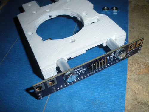
Light Bar Assembly Instructions
I am getting ready to sell a few of my new RepRap light bar kits and am providing assembly instructions here:
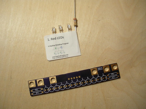
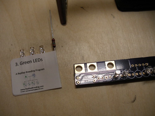
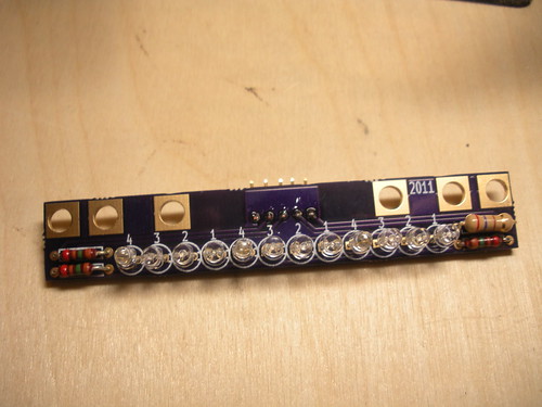
First verify you have all the parts:

The Red LEDs have a different resistor value than the rest. Ensure that this resistor stays with the Red LEDs.
Take the Red LEDs and resistor and bend the resistor leads to fit the holes on the PCB. The Red LEDs go in the spots marked "1" with the long LED leads going to the square shaped pads. The resistor goes in the spot marked "R1."
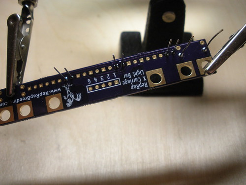
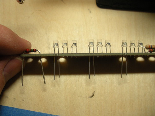
Solder them in place:
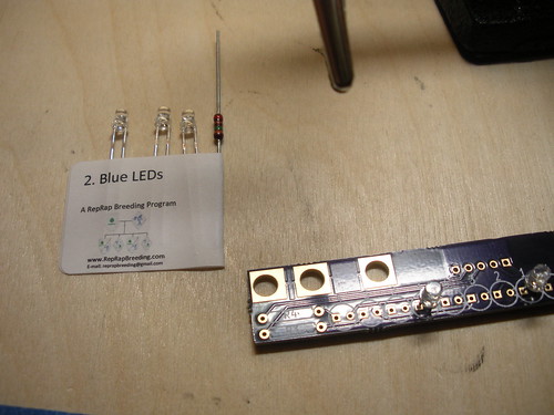
Repeat this for the remaining LEDs taking care to do them one color at a time to avoid mixing up the LEDs. They each have a number on the label that matches a number on the PCB.

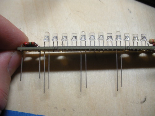
On the opposite side of the board place the 5 pin right angle header
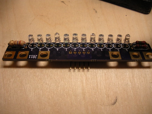
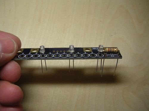
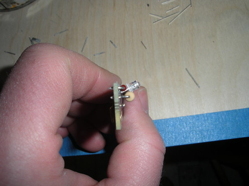
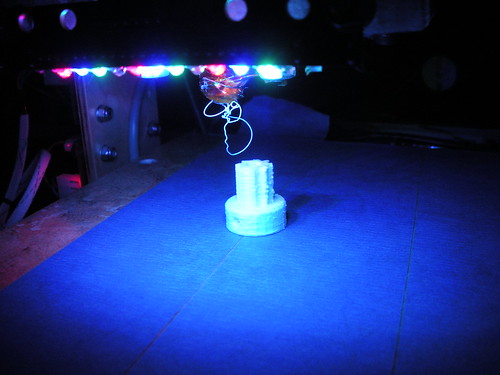
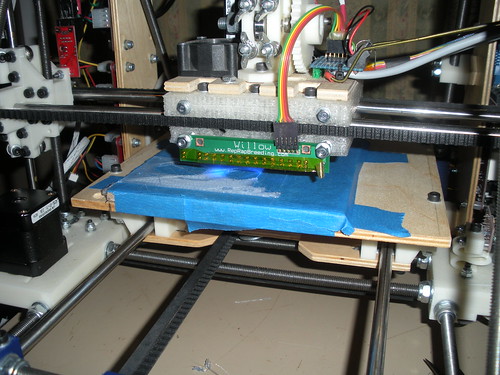
Then using the edge of a table or other flat object gently bend all the LEDs down to a 30-45° angle (The exact angle will depend on your carriage and hot end, so bend them to optimize the light on your print area.)
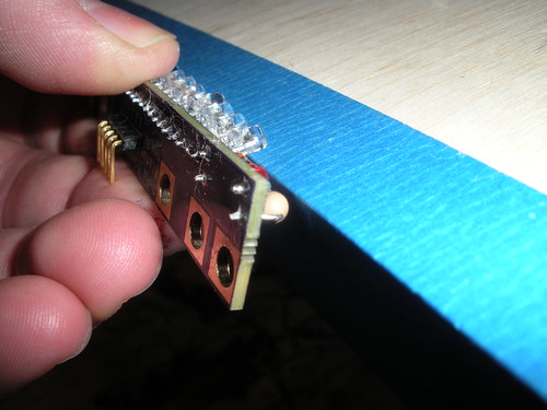
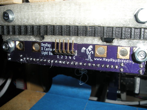
Mount it to your carriage connect the "G" pin to ground and the "1"-"4" pins to switched 12V (1 is Red, etc...).
More pictures here
First verify you have all the parts:
The Red LEDs have a different resistor value than the rest. Ensure that this resistor stays with the Red LEDs.
Take the Red LEDs and resistor and bend the resistor leads to fit the holes on the PCB. The Red LEDs go in the spots marked "1" with the long LED leads going to the square shaped pads. The resistor goes in the spot marked "R1."
Solder them in place:
Repeat this for the remaining LEDs taking care to do them one color at a time to avoid mixing up the LEDs. They each have a number on the label that matches a number on the PCB.
On the opposite side of the board place the 5 pin right angle header
Then using the edge of a table or other flat object gently bend all the LEDs down to a 30-45° angle (The exact angle will depend on your carriage and hot end, so bend them to optimize the light on your print area.)
Mount it to your carriage connect the "G" pin to ground and the "1"-"4" pins to switched 12V (1 is Red, etc...).
More pictures here
Sunday, February 27, 2011
Electronics setbacks, an 11th Prusa, & an OpenSCAD Workshop

It has been a while since my last post. I have been rather busy this quarter with my senior capstone project (Stay tuned for more on that later...)
I recently had a minor setback with my printer when something happened to my motherboard. I am not sure exactly what occurred but it became unresponsive and I could not re-flash it. I was not sure what to do except either replace the board or at least the Atmega644p. I was saved by Mark Ganter at Open3DP who had some spare Gen3 boards that needed TLC. I was able to find one that was in better shape than mine and get printing again. I still bought a new Atmega644p chip and plan to try repairing my original board. As much for the learning experience as anything else (I also hate to throw away something that could be fixed.)

I have now printed another complete Prusa (available on eMAKERshop) using the replacement board (the first picture is of this set).
I am teaching an OpenSCAD workshop at Metrix Create: Space on Sunday, March 27 from 2-4pm.
Saturday, January 29, 2011
A Ceramic Tile Print Bed - Part 2
I finally made time to pull off the old bed and drill the holes in the new tile. I always hate to mess with the printer unless it is broken, but I had waited long enough to find out how well the tile would work.
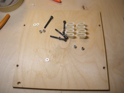
I had read some things about mounting the bed on only three points instead of four and thought that made sense. So I designed & printed a mount to attach to the froglet on the 180° side.

I then removed the bed and springs.
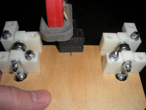
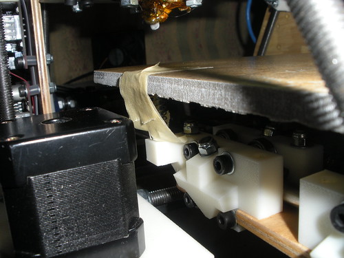
I decided that I could gain some height by cutting off the screws on the y carriage.

After blocking all the electronics I cut one screw off. I then decided that the amount of metal debris created was risky and removed the carriage to cut the remaining screws.
After cutting the screws off I drilled holes to mount the new support.
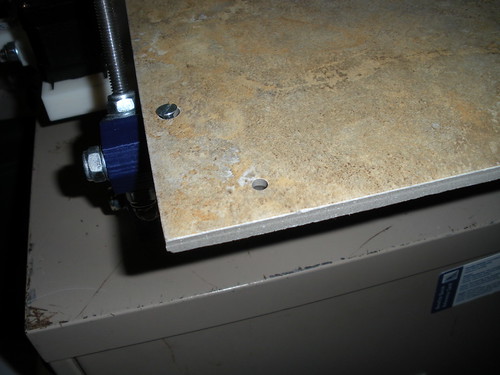
I then marked the first two hole on the tile and drilled them (under water).
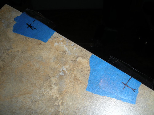
I then used the first two holes to locate the third

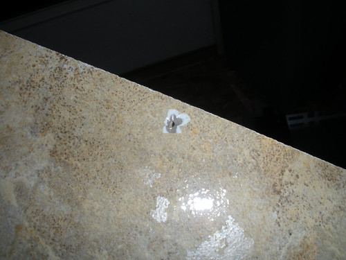
This last hole had a small amount of chip out on the top surface since I drilled it from the back. Most of this was removed when I drilled the countersink.
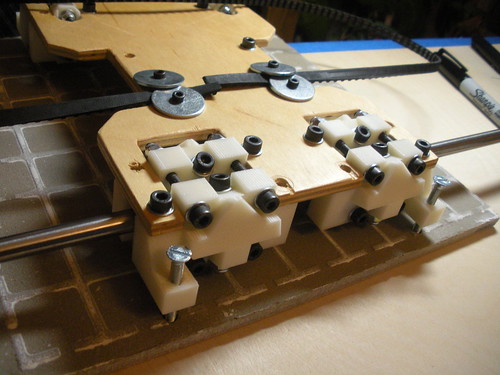
I then temporarily mounted the tile so I could mark and then drill the purge hole (at 0,0)
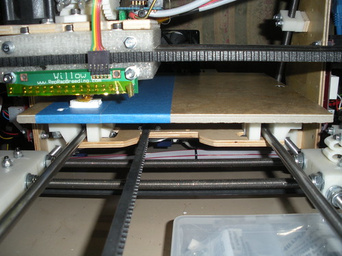
Finally, with the assistance of some tape, I mounted the bed using new springs.
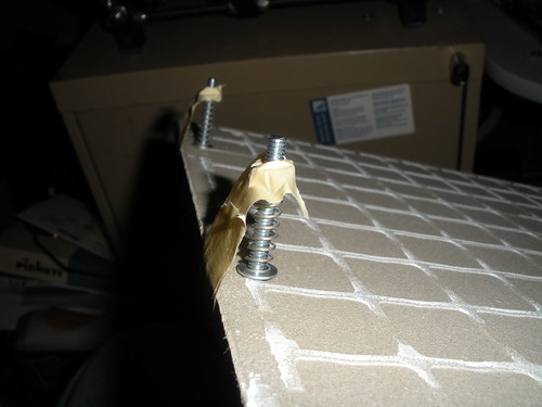
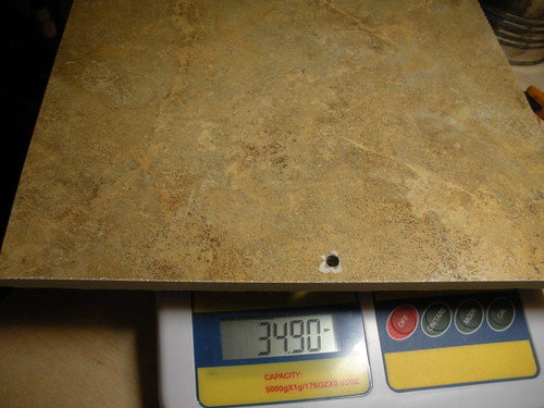
I gained almost 12mm of height:
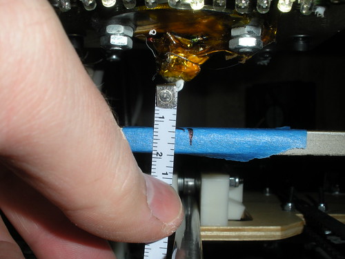
I am printing on it right now and it is working beautifully and is overall a very good success.
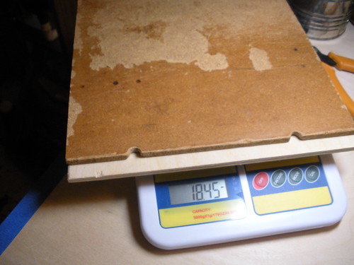
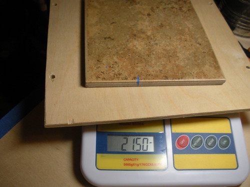
My only concerns are that the springs I am using are not quite as stiff as think I would like and I added some weight (about 13oz from where I was).
I had read some things about mounting the bed on only three points instead of four and thought that made sense. So I designed & printed a mount to attach to the froglet on the 180° side.

I then removed the bed and springs.
I decided that I could gain some height by cutting off the screws on the y carriage.
After blocking all the electronics I cut one screw off. I then decided that the amount of metal debris created was risky and removed the carriage to cut the remaining screws.
After cutting the screws off I drilled holes to mount the new support.
I then marked the first two hole on the tile and drilled them (under water).
I then used the first two holes to locate the third
This last hole had a small amount of chip out on the top surface since I drilled it from the back. Most of this was removed when I drilled the countersink.
I then temporarily mounted the tile so I could mark and then drill the purge hole (at 0,0)
Finally, with the assistance of some tape, I mounted the bed using new springs.
I gained almost 12mm of height:
I am printing on it right now and it is working beautifully and is overall a very good success.
My only concerns are that the springs I am using are not quite as stiff as think I would like and I added some weight (about 13oz from where I was).
Saturday, January 22, 2011
New light bar PCBs
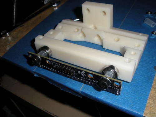
After making my last light bar I had a few people ask me about buying one. So I fixed the issues I had with my first iteration of the PCB and had 3 more made using DorkbotPDX's PCB service. These boards are much nicer than the one from BatchPCB and they came faster as well (it is also cheaper if you need 3 of each board).
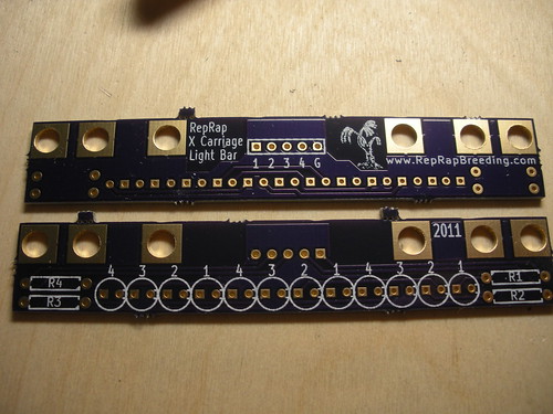
I love the purple solder mask and the silkscreen detail it very nice. I plan to assemble one of them to check that the changes I made to the PCB work as expected. After that I will have a production run made and have kits available to purchase.
It should now fit on a standard Mendel carriage, Rhys-Jones multi-material carriage, and a Prusa carriage.
I love the purple solder mask and the silkscreen detail it very nice. I plan to assemble one of them to check that the changes I made to the PCB work as expected. After that I will have a production run made and have kits available to purchase.
Wednesday, January 12, 2011
A Ceramic Tile Print Bed
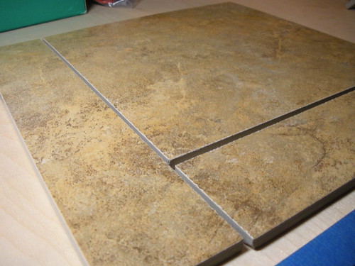
I was using a piece of polycarbonate that was to thin and was allowing parts to warp by lifting the PC sheet slightly. When thinking about stable, flat surfaces I realized ceramic tile could be a nice surface. So I went to my local home improvement store and bought a 6"x6" tile and tried it both plain and with blue tape on it. PLA did not stick to it alone but with the tape it works very well. It is very flat and stable, with the only downside I can see being that it is a little on the heavy side.
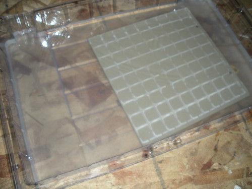
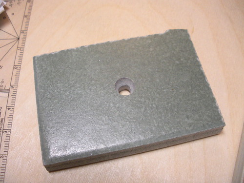
After proving to myself that it would work I thought about options for mounting a larger tile and tested drilling and countersinking holes in a scrap piece of tile I had.
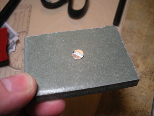
This also looks like it will work very nicely. My next step was to get a larger tile. The only problem here is that the Mendel print bed is not a standard tile size. However my local home improvement store will cut tile you buy there for free, at least small quantities, so I had them cut a 12" tile down to 9.5"x9.5" (which is a little bigger than the stock bed).
My next step is to drill the mounting holes, remove the wooden bed and mount my new tile bed. I am also thinking about adjusting the spring mount configuration to get a little more Z room and make the bed easily removable.
I may also do some testing with heating the tile as I think it would heat nicely as well.
After proving to myself that it would work I thought about options for mounting a larger tile and tested drilling and countersinking holes in a scrap piece of tile I had.
This also looks like it will work very nicely. My next step was to get a larger tile. The only problem here is that the Mendel print bed is not a standard tile size. However my local home improvement store will cut tile you buy there for free, at least small quantities, so I had them cut a 12" tile down to 9.5"x9.5" (which is a little bigger than the stock bed).
My next step is to drill the mounting holes, remove the wooden bed and mount my new tile bed. I am also thinking about adjusting the spring mount configuration to get a little more Z room and make the bed easily removable.
I may also do some testing with heating the tile as I think it would heat nicely as well.
Subscribe to:
Posts (Atom)


