Sunday, May 30, 2010

IT'S ALIVE!!!

I have fallen a little behind in posting the build.  So I am skipping the final assembly posts for now to let you all know that it is alive and printing.


It was officially alive Friday night (May 28, 2010) here is a picture of it's first extrusion.

It had a minor issue with jammed extrusion nozzle so after some minor surgery it was working again.
Not a perfect part, but still a part.


I then took it down to Metrix Create: Space on Saturday night for "MakerBot Night."   The very helpful people who were there were able to help me fix my firmware and adjust some other settings to get better results.


More adjustments and tweaks are needed but it is printing...
The thing on top is an experimental spool holder.  I will post the files for it on thingiverse soon.

And it has a name now, Willow.  If you are curious why do a web search for "blue and white willow."

I will get the final assembly posts up soon.

My Mendel Build (Y & Z-axis)

The Y-axis is basicaly stock.  The only real changes I made were reorienting a bolt in the motor mount.

The directions say that the one closest to the motor goes the other way.

The 360° bearing parts are a little challenging to get the washers in next to the bearings.

I ended up with three washers on each side of the center bearings on the 360° bearings and five washers on either side in the 180° bearings.


The only other change to the Y-axis was the wooden plate.  I cut this using a scroll saw, so I simplified the periphery.  I also eliminated the build plate notch and drip board.  In this picture you can see wooden y belt clamps.  I did not end up using them and will go into more detail about that when I get the the assembly section.  The other thing to not is that I only have two bolts in each bearing assembly.  I have left it with only two but moved one to the diagonal (inside).


Next came the Z-axis.  This had major changes. The tensioner was removed and the motor mount was combined with the lead screw base.
This was done by modifying Vik's OpenSCAD version of the lead screw base.  The other side just gets a lead screw base.

Finally I assembled the lead screws.  The change here was to use the different pulleys that have the integrated pulley washers.  I also used nylocks instead of the normal nuts called out.

 Next time I will talk about the frame and final assembly.

Sunday, May 23, 2010

My Mendel Build (X-axis)


My build began with the X-axis. The first part of that was the carriage.  

This still has the non-counter-bored bolt holes for the bearings on the bottom.  It was determined that there was no good reason to change them at this time.
The major change from the RepRap sites directions was not putting extra washers above the bearings.  The directions suggest putting 5 washers there.  I believe this may be to allow for a bolt that is not threaded far enough.  Then the upper carriage was assembled.

The other change to both of these parts was the horizontal bearing screws.  The directions say to use socket head screws from the outside with non-nylock nuts trapped in the carriage.  This was changed because we had surplus m4x20 hex bolts.
The four bolts at angles are long and one of them interfere with the extruder.  So they were trimmed using a rotary cut off wheel.
After the carriage I assembled the Idler bracket.
This has two main changes. First there is a third m4x40 bolt that is supposed to be in the middle.  This seems unnecessary and is difficult to install, so I excluded it.  Second the bolts that hold the bearings on are supposed to be m4x16, however they were too short so I used more of the extra m4x20 hex head bolts.


Next I assembled the 180° vertical bearing.  The directions say not to use nylocks anywhere they will be trapped because they may strip the holes.  This does not seem to be an issue with the part quality I am working with, so I used nylocks almost everywhere.

Then I proceeded to assemble the 360° vertical bearing.
 This should be assembled from one side across to the other.  This simplifies the installation of the bearing in the middle.
Next the motor bracket.  Before installing the motor n the bracket the gear was pressed on.  This was done using a vise.  A m4 nut was placed under the motor shaft to keep from damaging the motor.

The only change to this assembly was the bolts that hold the bearings on.  Just like on the idler bracket they are supposed to be m4x16, however I used m4x20 hex head bolts.

I did not assemble the separate pieces onto the rods at this time.  I will do that just before I am ready to install it in the frame.

Next time I will assemble the Y and Z-axis parts.

Wednesday, May 19, 2010

The design changes (or gears, feet, belt tensioners, and better hardware counts...)

One of the first changes we made, and one of the only changes made to O'Blue, was the gears.  The RepRap directions indicate that you file two sides of the motor shafts to fit the drive gears on them.

our new gear (left), stock gear (right)

This was determined to not be the best solution when we could just make new gears.  There are several modified gears on Thingiverse, but I developed a OpenSCAD script that allows you to import a STL file and specify the new hole size (and shape) and it plugs the old hole and cuts a new one.  This also allowed us to make a new gear for Wade's Extruder (as his had too large a hole for our motors).

The other changed gears where the Z-lead screw gears.  It was determined that the ones with combined rims were going to be better.


The next change that was made was to use Vik's Footed Vertex for the bottom four vertexes.  This eliminates a problem of the vertical drive shafts being the lowest point on the Mendel.  Since we discovered this problem after assembling most of the frame on O'Blue we ended up making add on feet for that Mendel.

Then another area of concern that I mentioned last time was the Z belt tensioner.  Four options were evaluated as follows:
Option 1. Use all stock parts and modify the tensioner
Option 2. Same as one but combine the tensioner with one lead-screw base and the motor mount with the other.  This eliminates two threaded rods.
Option 3. Eliminate the tensioner altogether and make the motor slide to adjust the tension.  This also eliminates two rods.
Option 4. Basically the same as Option 2 but allows the motor to adjust as well.

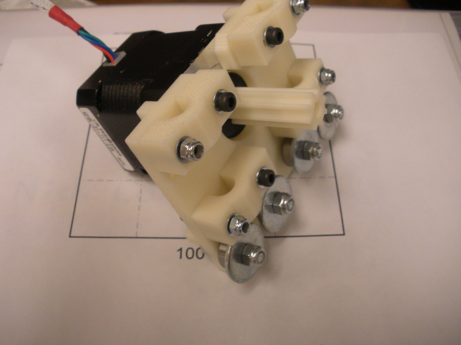
After evaluating these options it was decided that we would use option 3.  The new part looks like this (the other lead-screw base is basically stock):
This is based on the OpenSCAD version of the lead-screw base by Vik.  The one issue we have discovered is the hole for the opto-stop trapped nut is larger than the nuts we have so they spin freely.  Not a huge problem as we were able to jam the tip of a pair of needle-nose pliers in to hold the nut.  But it is something I will likely adjust before uploading my derivative work to Thingiverse.


This saved 2 rods and one RP part.  It also meant we would need a slightly shorter belt.  So we were going to order 35" belts, however they only had one so we ordered one 35" and one 36".  I will let you know later (when we have installed them) what length is best.

We then evaluated the hardware that was consumed in assembling O'Blue and modified the hardware list to minimize some waste.  Once again I plan to provide a optimized sourcing list in a later post once we have verified the changes we made work correctly.

Next time we start building....

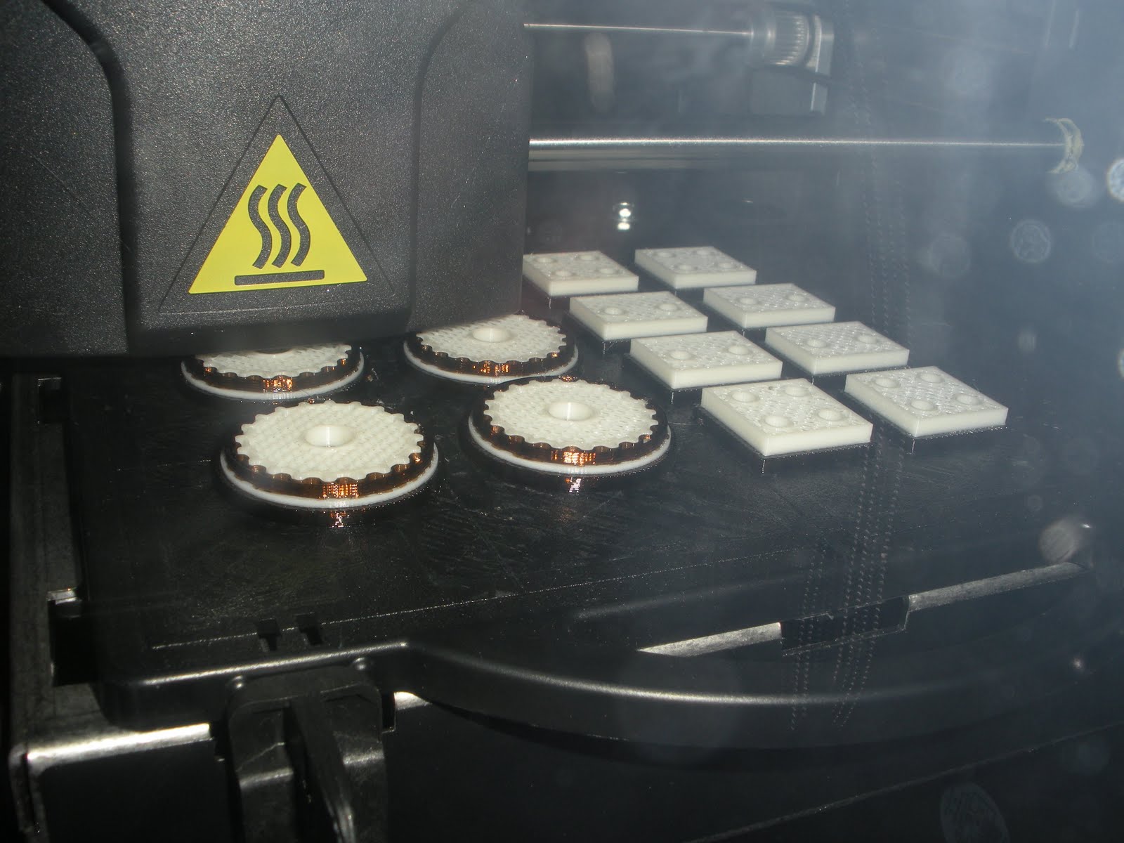
Now to leave you with some pictures of the new parts...

As I noted before mostly printed on the uPrint (in natural ABS) with a few parts from the 768BST (in blue ABS).

Saturday, May 15, 2010

O'Blue (Open3DP's Mendel)

This all started at the end of winter quarter 2010 in an advanced RP class where a group put together a MakerBot.  This started several conversations about building RepRaps and some different options for using the lab printers to make the RP parts.  These even included using the powder printers to make plaster parts.  There were two students who were very interested in exploring this during spring quarter (myself and Marcus Lew).

It was decided that the best approach was to build the lab a Mendel first and then procede to make two more using the lessons learned from the first one.  To that end, Professor Mark Ganter began printing parts for the labs Mendel using the labs Stratasys Dimension 768BST.  It was also decided that we should complete the first machine in time for the UW Engineering Discovery Days.

One of the first assemblies was the X carriage.

This has some odd features, due to printing constrants, such as the fact that the bolts sit at an angle and there is no recess to allow the head to sit flat.
The main frame was also started.
As the assembly progressed several other oddities were noted including spacers that are too short, but also not needed.

And the Z-axis tensioner sits higher than the rest of the belt path causing the belt to bind.  This was solved with additional washers.

z-axis tensioner is on the left

The biggest challenge was getting the electronics working properly.  We performed initial bench testing of the electronics before assembling them on the machine and everything seemed to be working. When the major assembly was complete we took the Mendel to Metrix Create: Space to get help with the final details.  Once these were complete we began testing the electronics and ran into intermittent issues with the stepper motors and could not get the extruder motor to turn.  At this point it was getting very late so we called it a night.

In the following days we were still unable to determine the problem ourselves so we asked our friends at Metrix for more help.  They spent some more time on it and determined that we had some bad solder joints and a bad extruder board, however they were able to get the machine working by the second day of the Discovery Days.  We had it printing parts and it got a lot of attention.

We then proceeded by figuring out exactly what changes we wanted to implement on our Mendels and what we needed to buy to get them going.  We were also able to get time on another commercial FDM printer to get some of our plastic parts printed.
 The first parts for the new Mendels

Next time I am planning to discuss the design changes we made.

Wednesday, May 12, 2010

What is a RepRap?

This was all started at Bath University in the UK by Adrian Bowyer.  The idea is to have a 3D printer that is capable of replicating most of its own parts.  This allows the machine to "reproduce."  Because of this concept the first machine design was named "Darwin" and the second was named "Mendel."  There is a wealth of information on the web about RepRaps and RepStraps (a printer made by conventional means that can produce RepRaps).  The best starting spot is the main RepRap web site.  Or if you are more interested in RepStraps, Makerbot sells kits that are a reasonable way to get started if you are less into tinkering.

This blog will focus on the construction of three Mendels.  The first was made as a lab Mendel in the Solheim Rapid Prototyping Laboratory @ the University of Washington.  The second and third are being made as personal printers for myself and Marcus, a fellow ME student.  The primary focus will be on my printer with some discussions about the others.

The first Mendel, O’Blue, had its plastic parts built on the labs Stratasys Dimension 768BST.
O'Blue

  Stratasys Dimension 768BST

So it is a first generation RepRap (not offspring of a RepRap).  The other two are also first generation RepRaps, but are half siblings with O'Blue as most of their parts were printed on a newer Dimension uPrint.

Dimension uPrint

  The new Mendels being printed on the uPrint

My next post will briefly discuss the build of O'Blue and some of the lessons we learned that we are applying to the new Mendels.  There are some pictures of O'Blue printing @ UW Engineering Discovery Days located on my other blog.